Fiber-optic-modules.com Offers
FE SFP, OC3 SFP, OC12 SFP, OC48 SFP, GIGABIT SFP, PON SFP, VIDEO SFP Modules.
Include WDM, CWDM, DWDM。
Friday, November 30, 2012
Friday, November 9, 2012
Commonly used in the optical module of the Ethernet switch

SFP, GBIC, XFP, XENPAK. Their full name in English, Chinese name is not used, can be as simple as understanding the
SFP: Small Form-factor Pluggable transceiver, small form-factor pluggable transceiver
GBIC: GigaBit Interface Converter, Gigabit Ethernet interface converter
XFP: 10-Gigabit small Form-factor Pluggable transceiver Gigabit Ethernet interface small form-factor pluggable transceiver
XENPAK: a collection of 10-Gigabit EtherNet the Transceiver PAcKage Gigabit Ethernet interface transceiver package
In accordance with the rate: Ethernet applications 100Base (Fast) 1000Base (Gigabit) 10GE SDH applications 155M, 622M, 2.5G, 10G
According to the package points: 1 × 9, SFF, SFP, GBIC, XENPAK, XFP, package see
1 × 9 package - welding optical module, the general speed is not higher than gigabit, multi-SC interface
SFF package - welding small package optical modules, general speed is not higher than gigabit, multi-LC interface
GBIC Package - hot-swappable Gigabit Interface optical module, SC connector
SFP package - hot-plug small package module, the maximum data rate of up to 4G, the use of LC interface
XENPAK package - applications in the Gigabit Ethernet SC interface
XFP package - 10G optical modules that can be used in Gigabit Ethernet, SONET and other systems.
the use of LC interface To sub: LED, VCSEL, FP LD, DFB L
in accordance with the type of laser Points in accordance with the emission wavelength: 850 nm, 1310nm, 1550nm, etc. Use: non-hot-plug (1 × 9, SFF), hot-swappable (GBIC, SFP, XENPAK, XFP)
Sunday, October 14, 2012
Fiber optic modules supplier
There is a website about fiber optic modules. You can findout the information what you want.
WebSiteUrl:http://www.fiber-optic-modules.com
Or you can visit it click fiber optic modules
Shenzhen Sopto Technology Co., Limited referred to Sopto, is a
professional fiber optic communications technology company which engaged
in manufacturing and marketing fiber optic products. It is located in
Shenzhen City, Guangdong Province, China. Sopto has large factories and
one trading company. The factories mainly produce fiber optic modules,
twinax cables, media converter, PCI-E card, FTTH and fiber optic the
patch cords and other related passive products.
After years of development, we formed the operation pattern of four
core self-produce products mentioned above, supplemented by a variety of
superior products. We have Rohs, CE, FC, SGS certification, provide
fiber-optic communications agents, retailers, and telecommunications
operators worldwide high quality and reliable fiber optic products,
including fiber optic modules, Media converters and chassis, PDH Fiber
Optical Multiplexer and Protocol Converters, GEPON and GPON Solution,
Splitter CWDM DWDM, PCI-E Cards, Fiber Optical Patch Cords and Cables,
Fiber Optical Adaptor and Attenuators and so on. What’s worth to noting
is that our fiber optic modules are compatible with Cisco, 3com, Juniper
and other brands of fiber optic equipment.
WebSiteUrl:http://www.fiber-optic-modules.com
Or you can visit it click fiber optic modules
Monday, May 7, 2012
Transaction Descriptor Overview
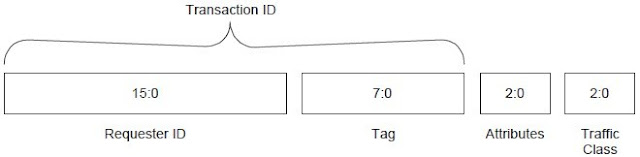
The Transaction Descriptor is a mechanism for carrying Transaction information between the
Requester and the Completer. Transaction Descriptors are composed of three fields:
Transaction ID – identifies outstanding Transactions
Attributes field – specifies characteristics of the Transaction
Traffic Class (TC) field – associates Transaction with type of required service
Figure 2-12 shows the fields of the Transaction Descriptor. Note that these fields are shown
together to highlight their relationship as parts of a single logical entity. The fields are not
contiguous in the packet header.
Figure 2-12: Transaction Descriptor
Sunday, May 6, 2012
First/Last DW Byte Enables Rules
Byte Enables are included with Memory, I/O, and Configuration Requests. This section defines the corresponding rules. Byte Enables, when present in the Request header, are located in byte 7 of the header (see Figure 2-11). For Memory Read Requests that have the TH bit Set, the Byte Enable fields are repurposed to carry the ST[7:0] field, and values for the Byte Enables are implied as defined below. Such Requests must only be issued when it is acceptable to complete the Requests as if all bytes for requested payload were enabled.
For Memory Reads that have the TH bit Set, the following values are implied for the Byte
Enables.
• If the Length field for this Request indicates a length of 1 DW, then the value for the 1st DW
Byte Enables is implied to be 1111b and the value for the Last DW Byte Enables is implied
to be 0000b.
• If the Length field for this Request indicates a length of greater than 1 DW, then the value
for the 1st DW Byte Enables and the Last DW Byte Enables is implied to be 1111b.
The 1st DW BE[3:0] field contains Byte Enables for the first (or only) DW referenced by a
Request.
• If the Length field for a Request indicates a length of greater than 1 DW, this field must not
equal 0000b.
The Last DW BE[3:0] field contains Byte Enables for the last DW of a Request.
• If the Length field for a Request indicates a length of 1 DW, this field must equal 0000b.
• If the Length field for a Request indicates a length of greater than 1 DW, this field must not
equal 0000b.
For each bit of the Byte Enables fields:
• a value of 0b indicates that the corresponding byte of data must not be written or, if nonprefetchable, must not be read at the Completer.
• a value of 1b indicates that the corresponding byte of data must be written or read at the
Completer.
Non-contiguous Byte Enables (enabled bytes separated by non-enabled bytes) are permitted in the 1st DW BE field for all Requests with length of 1 DW.
• Non-contiguous Byte Enable examples: 1010b, 0101b, 1001b, 1011b, 1101b
Non-contiguous Byte Enables are permitted in both Byte Enables fields for QW aligned
Memory Requests with length of 2 DW (1 QW).
All non-QW aligned Memory Requests with length of 2 DW (1 QW) and Memory Requests with
length of 3 DW or more must enable only bytes that are contiguous with the data between the first and last DW of the Request.
• Contiguous Byte Enables examples:
1st DW BE: 1100b, Last DW BE: 0011b
1st DW BE: 1000b, Last DW BE: 0111b
Table 2-9 shows the correspondence between the bits of the Byte Enables fields, their location in the Request header, and the corresponding bytes of the referenced data.
A Write Request with a length of 1 DW with no bytes enabled is permitted, and has no effect at the Completer.
If a Read Request of 1 DW specifies that no bytes are enabled to be read (1st DW BE[3:0] field = 0000b), the corresponding Completion must specify a Length of 1 DW, and include a data payload of 1 DW
• The contents of the data payload within the Completion packet is unspecified and may be
any value
Receiver/Completer behavior is undefined for a TLP violating the Byte Enables rules specified in this section.
Receivers may optionally check for violations of the Byte Enables rules specified in this section. If a Receiver implementing such checks determines that a TLP violates one or more Byte Enables rules, the TLP is a Malformed TLP
• If Byte Enables rules are checked, a violation is a reported error associated with the
Receiving Port (see Section 6.2)
The flush semantic has wide application, and all Completers must implement the functionality associated with this semantic. Because a Requester may use the flush semantic without comprehending the characteristics of the Completer, Completers must ensure that zero-length reads do not have side-effects. This is really just a specific case of the rule that in a non-prefetchable space, non-enabled bytes must not be read at the Completer. Note that the flush applies only to traffic in the same Traffic Class as the zero-length Read.
Friday, May 4, 2012
Routing and Addressing Rules
There are three principal mechanisms for TLP routing: address, ID, and implicit. This section defines the rules for the address and ID routing mechanisms. Implicit routing is used only with Message Requests, and is covered in Section 2.2.8.
Address routing is used with Memory and I/O Requests.

Figure 2-8: 32-bit Address Routing


Address Based Routing Rules
Address routing is used with Memory and I/O Requests.
Two address formats are specified, a 64-bit format used with a 4 DW header (see Figure 2-7) and a 32-bit format used with a 3 DW header (see Figure 2-8).
Figure 2-8: 32-bit Address Routing
For Memory Read, Memory Write, and AtomicOp Requests, the Address Type (AT) field is encoded as shown in Table 2-5, with full descriptions contained in the Address Translation Services Specification, Revision 1.0. For all other Requests, the AT field is reserved.
Table 2-5: Address Type (AT) Field Encodings
Address mapping to the TLP header is shown in Table 2-6.
Table 2-6: Address Field Mapping
Memory Read, Memory Write, and AtomicOp Requests can use either format.
• For Addresses below 4 GB, Requesters must use the 32-bit format. The behavior of the receiver is not specified if a 64-bit format request addressing below 4 GB (i.e., with the upper 32 bits of address all 0) is received.
I/O Read Requests and I/O Write Requests use the 32-bit format.
All agents must decode all address bits in the header - address aliasing is not allowed.
ID Based Routing Rules
ID routing is used with Configuration Requests,with ID Routed Messages, and with
Completions. This specification defines Vendor_Defined Messages that are ID Routed (Section 2.2.8.6). Other specifications define additional ID Routed Messages.
Completions. This specification defines Vendor_Defined Messages that are ID Routed (Section 2.2.8.6). Other specifications define additional ID Routed Messages.
ID routing uses the Bus, Device, and Function Numbers (as applicable) to specify the destination for the TLP:
• For non-ARI Routing IDs, Bus, Device, and (3-bit) Function Number to TLP header
mapping is shown in Table 2-7.
• For ARI Routing IDs, the Bus and (8-bit) Function Number to TLP header mapping is shown in Table 2-8.
• For non-ARI Routing IDs, Bus, Device, and (3-bit) Function Number to TLP header
mapping is shown in Table 2-7.
• For ARI Routing IDs, the Bus and (8-bit) Function Number to TLP header mapping is shown in Table 2-8.
Two ID routing formats are specified, one used with a 4 DW header (see Figure 2-9) and one used with a 3 DW header (see Figure 2-10).
• Header field locations are the same for both formats, and are given in Table 2-7
• Header field locations are the same for both formats, and are given in Table 2-7
Table 2-7: Header Field Locations for non-ARI ID Routing
Table 2-8: Header Field Locations for ARI ID Routing
Figure 2-9: ID Routing with 4 DW Header
Figure 2-10: ID Routing with 3 DW Header
Thursday, May 3, 2012
TLP Digest Rules
For any TLP, a value of 1b in the TD field indicates the presence of the TLP Digest field including an ECRC value at the end of the TLP
• A TLP where the TD field value does not correspond with the observed size (accounting for the data payload, if present) is a Malformed TLP
♦ This is a reported error associated with the Receiving Port (see Section 6.2)
If an intermediate or ultimate PCI Express Receiver of the TLP does not support ECRC checking, the Receiver must ignore the TLP Digest4
• If the Receiver of the TLP supports ECRC checking, the Receiver interprets the value in the TLP Digest field as an ECRC value, according to the rules in Section 2.7.1
Sunday, April 22, 2012
TLPs with Data Payloads - Rules
Length is specified as an integral number of DW
Length[9:0] is reserved for all Messages except those which explicitly refer to a Data Length
• Refer to the Message Code tables in Section 2.2.8.
The Transmitter of a TLP with a data payload must not allow the data payload length as given
by the TLP’s Length [ ] field to exceed the length specified by the value in the
Max_Payload_Size field of the Transmitter’s Device Control register taken as an integral number
of DW (see Section 7.8.4).
• For ARI Devices, the Max_Payload_Size is determined solely by the setting in Function 0.
The Max_Payload_Size settings in other Functions are ignored.
• For an Upstream Port associated with a non-ARI multi-Function device whose
Max_Payload_Size settings are identical across all Functions, a transmitted TLP’s data
payload must not exceed the common Max_Payload_Size setting.
• For an Upstream Port associated with a non-ARI multi-Function device whose
Max_Payload_Size settings are not identical across all Functions, a transmitted TLP’s data
payload must not exceed a Max_Payload_Size setting whose determination is
implementation specific.
♦ Transmitter implementations are encouraged to use the Max_Payload_Size setting from
the Function that generated the transaction, or else the smallest Max_Payload_Size
setting across all Functions.
♦ Software should not set the Max_Payload_Size in different Functions to different values
unless software is aware of the specific implementation.
• Note: Max_Payload_Size applies only to TLPs with data payloads; Memory Read Requests
are not restricted in length by Max_Payload_Size. The size of the Memory Read Request is
controlled by the Length field
The size of the data payload of a Received TLP as given by the TLP’s Length [ ] field must not
exceed the length specified by the value in the Max_Payload_Size field of the Receiver’s Device
Control register taken as an integral number of DW (see Section 7.8.4).
• Receivers must check for violations of this rule. If a Receiver determines that a TLP violates
this rule, the TLP is a Malformed TLP
♦ This is a reported error associated with the Receiving Port (see Section 6.2)
• For ARI Devices, the Max_Payload_Size is determined solely by the setting in Function 0.20 The Max_Payload_Size settings in other Functions are ignored.
• For an Upstream Port associated with a non-ARI multi-Function device whose
Max_Payload_Size settings are identical across all Functions, the Receiver is required to
check the TLP’s data payload size against the common Max_Payload_Size setting.
• For an Upstream Port associated with a non-ARI multi-Function device whose
Max_Payload_Size settings are not identical across all Functions, the Receiver is required to
check the TLP’s data payload against a Max_Payload_Size setting whose determination is
implementation specific.
♦ Receiver implementations are encouraged to use the Max_Payload_Size setting from the
Function targeted by the transaction, or else the largest Max_Payload_Size setting across all Functions.
♦ Software should not set the Max_Payload_Size in different Functions to different values
unless software is aware of the specific implementation.
For TLPs, that include data, the value in the Length field and the actual amount of data included
in the TLP must match.
• Receivers must check for violations of this rule. If a Receiver determines that a TLP violates
this rule, the TLP is a Malformed TLP
♦ This is a reported error associated with the Receiving Port (see Section 6.2)
The value in the Length field applies only to data – the TLP Digest is not included in the Length
When a data payload is included in a TLP other than an AtomicOp Request or an AtomicOp
Completion, the first byte of data following the header corresponds to the byte address closest
to zero and the succeeding bytes are in increasing byte address sequence.
• Example: For a 16-byte write to location 100h, the first byte following the header would be
the byte to be written to location 100h, and the second byte would be written to location
101h, and so on, with the final byte written to location 10Fh.
The data payload in AtomicOp Requests and AtomicOp Completions must be formatted such
that the first byte of data following the TLP header is the least significant byte of the first data
value, and subsequent bytes of data are strictly increasing in significance. With CAS Requests,
the second data value immediately follows the first data value, and must be in the same format.
• The endian format used by AtomicOp Completers to read and write data at the target
location is implementation specific, and is permitted to be whatever the Completer
determines is appropriate for the target memory (e.g., little endian, big endian, etc). Endian
format capability reporting and controls for AtomicOp Completers are outside the scope of
this specification.
• Little endian example: For a 64-bit (8-byte) Swap Request targeting location 100h with the
target memory in little endian format, the first byte following the header is written to
location 100h, the second byte is written to location 101h, and so on, with the final byte
written to location 107h. Note that before performing the writes, the Completer first reads
the target memory locations so it can return the original value in the Completion. The byte
address correspondence to the data in the Completion is identical to that in the Request.
• Big endian example: For a 64-bit (8-byte) Swap Request targeting location 100h with the
target memory in big endian format, the first byte following the header is written to location
107h, the second byte is written to location 106h, and so on, with the final byte written to
location 100h. Note that before performing the writes, the Completer first reads the target
memory locations so it can return the original value in the Completion. The byte address
correspondence to the data in the Completion is identical to that in the Request.
• Figure 2-6 shows little endian and big endian examples of Completer target memory access
for a 64-bit (8-byte) FetchAdd. The bytes in the operands and results are numbered 0-7,
with byte 0 being least significant and byte 7 being most significant. In each case, the
Completer fetches the target memory operand using the appropriate endian format. Next,
AtomicOp compute logic in the Completer performs the FetchAdd operation using the
original target memory value and the “add” value from the FetchAdd Request. Finally, the
Completer stores the FetchAdd result back to target memory using the same endian format
used for the fetch.
A-0742
7 6 5 4 3 2 1 0
7 6 5 4 3 2 1 0
7 6 5 4 3 2 1 0
AtomicOp
compute
logic
target memory
locations
FetchAdd example with target
memory in little endian format
107h
106h
105h
104h
103h
102h
101h
100h
"add" value
FetchAdd result
original value
7 6 5 4 3 2 1 0
7 6 5 4 3 2 1 0
7 6 5 4 3 2 1 0
AtomicOp
compute
logic
target memory
locations
FetchAdd example with target
memory in big endian format
107h
106h
105h
104h
103h
102h
101h
100h
"add" value
FetchAdd result
original value
Figure 2-6: Examples of Completer Target Memory Access for FetchAdd
IMPLEMENTATION NOTE
Endian Format Support by RC AtomicOp Completers
One key reason for permitting an AtomicOp Completer to access target memory using an endian
format of its choice is so that PCI Express devices targeting host memory with AtomicOps can
interoperate with host software that uses atomic operation instructions (or instruction sequences).
Some host environments have limited endian format support with atomic operations, and by
supporting the “right” endian format(s), an RC AtomicOp Completer may significantly improve
interoperability.
For an RC with AtomicOp Completer capability on a platform supporting little-endian-only
processors, there is little envisioned benefit for the RC AtomicOp Completer to support any endian
format other than little endian. For an RC with AtomicOp Completer capability on a platform
supporting bi-endian processors, there may be benefit in supporting both big endian and little
endian formats, and perhaps having the endian format configurable for different regions of host
memory.
There is no PCI Express requirement that an RC AtomicOp Completer support the host processor’s
“native” format (if there is one), nor is there necessarily significant benefit to doing so. For
example, some processors can use load-link/store-conditional or similar instruction sequences to do
atomic operations in non-native endian formats and thus not need the RC AtomicOp Completer to
support alternative endian formats.
IMPLEMENTATION NOTE
Maintaining Alignment in Data Payloads
Section 2.3.1.1 discusses rules for forming Read Completions respecting certain natural address
boundaries. Memory Write performance can be significantly improved by respecting similar address
boundaries in the formation of the Write Request. Specifically, forming Write Requests such that
natural address boundaries of 64 or 128 bytes are respected will help to improve system
performance.
Friday, April 20, 2012
Common Packet Header Fields
All Transaction Layer Packet (TLP) prefixes and headers contain the following fields (see
Figure 2-4):
Fmt[2:0] – Format of TLP (see Table 2-2) – bits 7:5 of byte 0
Type[4:0] – Type of TLP – bits 4:0 of byte 0
A-0784
Byte 0 > Fmt Type {Fields in bytes 1 through 3 depend on Fmt and Type Fields
+0 +1 +2 +3
7 6 5 4 3 2 1 0 7 6 5 4 3 2 1 0 7 6 5 4 3 2 1 0 7 6 5 4 3 2 1 0
Figure 2-4: Fields Present in All TLPs
The Fmt field(s) indicate the presence of one or more TLP Prefixes and the Type field(s) indicates
the associated TLP Prefix type(s).
The Fmt and Type fields of the TLP Header provide the information required to determine the size
of the remaining part of the TLP Header, and if the packet contains a data payload following the
header.
The Fmt, Type, TD, and Length fields of the TLP Header contain all information necessary to
determine the overall size of the non-prefix portion of the TLP. The Type field, in addition to
defining the type of the TLP also determines how the TLP is routed by a Switch. Different types of
TLPs are discussed in more detail in the following sections.
Permitted Fmt[2:0] and Type[4:0] field values are shown in Table 2-3.
• All other encodings are reserved (see Section 2.3).
TC[2:0] – Traffic Class (see Section 2.4.2) – bits [6:4] of byte 1
TH – 1b indicates the presence of TLP Processing Hints (TPH) in the TLP header and optional
TPH TLP Prefix (if present) – bit 0 of byte 1 (see Section 2.2.7.1)
Attr[1:0] – Attributes (see Section 2.2.6.3) – bits [5:4] of byte 2
Attr[2] – Attribute (see Section 2.2.6.3) – bit 2 of byte 1
TD – 1b indicates presence of TLP digest in the form of a single DW at the end of the TLP (see Section 2.2.3) – bit 7 of byte 2
EP – indicates the TLP is poisoned (see Section 2.7) – bit 6 of byte 2
Length[9:0] – Length of data payload in DW (see Table 2-4) – bits 1:0 of byte 2 concatenated
with bits 7:0 of byte 3
• TLP data must be 4-byte naturally aligned and in increments of 4-byte Double Words (DW).
• Reserved for TLPs that do not contain or refer to data payloads, including Cpl, CplLk, and
Messages (except as specified)
OM14540B
7 6 5 4 3 2 1 0 7 6 5 4 3 2 1 0 7 6 5 4 3 2 1 0 7 6 5 4 3 2 1 0
Attr TD
EP
Type R TC AT Length
+0 +1 +2 +3
Byte 0 > TH
Fmt R R
Figure 2-5: Fields Present in All TLP Headers
Table 2-2: Fmt[1:0] Field Values
Fmt[1:0] Corresponding TLP Format
000b 3 DW header, no data
001b 4 DW header, no data
010b 3 DW header, with data
011b 4 DW header, with data
100b TLP Prefix
All encodings not shown above are
reserved (see Section 2.3).
Table 2-3: Fmt[1:0] and Type[4:0] Field Encodings
TLP Type Fmt
[2:0]2
(b)
Type
[4:0]
(b)
Description
MRd 000
001
0 0000 Memory Read Request
MRdLk 000
001
0 0001 Memory Read Request-Locked
MWr 010
011
0 0000 Memory Write Request
IORd 000 0 0010 I/O Read Request
IOWr 010 0 0010 I/O Write Request
CfgRd0 000 0 0100 Configuration Read Type 0
CfgWr0 010 0 0100 Configuration Write Type 0
CfgRd1 000 0 0101 Configuration Read Type 1
CfgWr1 010 0 0101 Configuration Write Type 1
TCfgRd 000 1 1011 Deprecated TLP Type3
TCfgWr 010 1 1011 Deprecated TLP Type3
Msg 001
1 0r2r1r0 Message Request – The sub-field r[2:0]
specifies the Message routing mechanism
(see Table 2-18).
MsgD 011
1 0r2r1r0 Message Request with data payload – The
sub-field r[2:0] specifies the Message
routing mechanism (see Table 2-18).
Cpl 000 0 1010 Completion without Data – Used for I/O and
Configuration Write Completions with any
Completion Status. Also used for AtomicOp
Completions and Read Completions (I/O,
Configuration, or Memory) with Completion
Status other than Successful Completion.
CplD 010 0 1010 Completion with Data – Used for Memory,
I/O, and Configuration Read Completions.
Also used for AtomicOp Completions.
CplLk 000 0 1011 Completion for Locked Memory Read
without Data – Used only in error case.
CplDLk 010 0 1011 Completion for Locked Memory Read –
otherwise like CplD.
2 Requests with two Fmt[2:0] values shown can use either 32 bits (the first value) or 64 bits (the second value)
Addressing Packet formats.
3 Deprecated TLP Types: previously used for TCS, which is no longer supported by this specification. If a Receiver
does not implement TCS, the Receiver must treat such Requests as Malformed Packets.
TLP Type Fmt
[2:0]2
(b)
Type
[4:0]
(b)
Description
FetchAdd 010
011
0 1100 Fetch and Add AtomicOp Request
Swap 010
011
0 1101 Unconditional Swap AtomicOp Request
CAS 010
011
0 1110 Compare and Swap AtomicOp Request
LPrfx 100 0L3L2L1L0 Local TLP Prefix – The sub-field L[3:0]
specifies the Local TLP Prefix type (see
Table 2-29).
EPrfx 100 1E3E2E1E0 End-End TLP Prefix – The sub-field E[3:0]
specifies the End-End TLP Prefix type (see
Table 2-30).
All encodings not shown above are
reserved (see Section 2.3).
Table 2-4: Length[9:0] Field Encoding
Length[9:0] Corresponding TLP Data Payload Size
00 0000 0001b 1 DW
00 0000 0010b 2 DW
... ...
11 1111 1111b 1023 DW
00 0000 0000b 1024 DW
Wednesday, April 18, 2012
Transaction Layer Protocol - Packet Definition
PCI Express uses a packet based protocol to exchange information between the Transaction Layers
of the two components communicating with each other over the Link. PCI Express supports the
following basic transaction types: Memory, I/O, Configuration, and Messages. Two addressing
formats for Memory Requests are supported: 32 bit and 64 bit.Transactions are carried using Requests and Completions. Completions are used only where
required, for example, to return read data, or to acknowledge Completion of I/O and Configuration
Write Transactions. Completions are associated with their corresponding Requests by the value in
the Transaction ID field of the Packet header.
All TLP fields marked Reserved (sometimes abbreviated as R) must be filled with all 0’s when a TLP is formed. Values in such fields must be ignored by Receivers and forwarded unmodified by
Switches. Note that for certain fields there are both specified and reserved values – the handling of
reserved values in these cases is specified separately for each case.
Monday, April 16, 2012
Fiber optic preform
A preform is a piece of glass used to draw an optical fiber. The
preform may consist of several pieces of a glass with different refractive indices, to provide the core and cladding of the fiber. The shape of the preform may be circular, although for some applications such as double-clad fibers another form is preferred.[61] In fiber lasers based on double-clad fiber, an asymmetric shape improves the filling factor for laser pumping.
Because of the surface tension, the shape is smoothed during the drawing process, and the shape of the resulting fiber does not reproduce the sharp edges of the preform. Nevertheless, the careful polishing of the preform is important, any defects of the preform surface affect the optical and mechanical properties of the resulting fiber. In particular, the preform for the test-fiber shown in the figure was not polished well, and the cracks are seen with confocal optical microscope.
Because of the surface tension, the shape is smoothed during the drawing process, and the shape of the resulting fiber does not reproduce the sharp edges of the preform. Nevertheless, the careful polishing of the preform is important, any defects of the preform surface affect the optical and mechanical properties of the resulting fiber. In particular, the preform for the test-fiber shown in the figure was not polished well, and the cracks are seen with confocal optical microscope.
Other uses of optical fibers

Fibers are widely used in illumination applications. They are used as light guides in medical and other applications where bright light needs to be shone on a target without a clear line-of-sight path. In some buildings, optical fibers route sunlight from the roof to other parts of the building (see nonimaging optics). Optical fiber illumination is also used for decorative applications, including signs, art, toys and artificial Christmas trees. Swarovski boutiques use optical fibers to illuminate their crystal showcases from many different angles while only employing one light source. Optical fiber is an intrinsic part of the light-transmitting concrete building product, LiTraCon.
Optical fiber is also used in imaging optics. A coherent bundle of fibers is used, sometimes along with lenses, for a long, thin imaging device called an endoscope, which is used to view objects through a small hole. Medical endoscopes are used for minimally invasive exploratory or surgical procedures. Industrial endoscopes (see fiberscope or borescope) are used for inspecting anything hard to reach, such as jet engine interiors. Many microscopes use fiber-optic light sources to provide intense illumination of samples being studied.
In spectroscopy, optical fiber bundles transmit light from a spectrometer to a substance that cannot be placed inside the spectrometer itself, in order to analyze its composition. A spectrometer analyzes substances by bouncing light off of and through them. By using fibers, a spectrometer can be used to study objects remotely.[31][32][33]
An optical fiber doped with certain rare earth elements such as erbium can be used as the gain medium of a laser or optical amplifier. Rare-earth doped optical fibers can be used to provide signal amplification by splicing a short section of doped fiber into a regular (undoped) optical fiber line. The doped fiber is optically pumped with a second laser wavelength that is coupled into the line in addition to the signal wave. Both wavelengths of light are transmitted through the doped fiber, which transfers energy from the second pump wavelength to the signal wave. The process that causes the amplification is stimulated emission.
Optical fibers doped with a wavelength shifter collect scintillation light in physics experiments.
Optical fiber can be used to supply a low level of power (around one watt)[citation needed] to electronics situated in a difficult electrical environment. Examples of this are electronics in high-powered antenna elements and measurement devices used in high voltage transmission equipment.
The iron sights for handguns, rifles, and shotguns may use short pieces of optical fiber for contrast enhancement.
Fiber optic sensors
Main article: Fiber optic sensor
Fibers have many uses in remote sensing. In some applications, the sensor is itself an optical fiber. In other cases, fiber is used to connect a non-fiberoptic sensor to a measurement system. Depending on the application, fiber may be used because of its small size, or the fact that no electrical power is needed at the remote location, or because many sensors can be multiplexed along the length of a fiber by using different wavelengths of light for each sensor, or by sensing the time delay as light passes along the fiber through each sensor. Time delay can be determined using a device such as an optical time-domain reflectometer.
Optical fibers can be used as sensors to measure strain, temperature, pressure and other quantities by modifying a fiber so that the property to measure modulates the intensity, phase, polarization, wavelength, or transit time of light in the fiber. Sensors that vary the intensity of light are the simplest, since only a simple source and detector are required. A particularly useful feature of such fiber optic sensors is that they can, if required, provide distributed sensing over distances of up to one meter.
Extrinsic fiber optic sensors use an optical fiber cable, normally a multi-mode one, to transmit modulated light from either a non-fiber optical sensor—or an electronic sensor connected to an optical transmitter. A major benefit of extrinsic sensors is their ability to reach otherwise inaccessible places. An example is the measurement of temperature inside aircraft jet engines by using a fiber to transmit radiation into a radiation pyrometer outside the engine. Extrinsic sensors can be used in the same way to measure the internal temperature of electrical transformers, where the extreme electromagnetic fields present make other measurement techniques impossible. Extrinsic sensors measure vibration, rotation, displacement, velocity, acceleration, torque, and twisting. A solid state version of the gyroscope, using the interference of light, has been developed. The fiber optic gyroscope (FOG) has no moving parts, and exploits the Sagnac effect to detect mechanical rotation.
Common uses for fiber optic sensors includes advanced intrusion detection security systems. The light is transmitted along a fiber optic sensor cable placed on a fence, pipeline, or communication cabling, and the returned signal is monitored and analysed for disturbances. This return signal is digitally processed to detect disturbances and trip an alarm if an intrusion has occurred.
Fiber optic Application
Optical fiber communication
Main article: Fiber-optic communication
Optical fiber can be used as a medium for telecommunication and computer networking because it is flexible and can be bundled as cables. It is especially advantageous for long-distance communications, because light propagates through the fiber with little attenuation compared to electrical cables. This allows long distances to be spanned with few repeaters. Additionally, the per-channel light signals propagating in the fiber have been modulated at rates as high as 111 gigabits per second by NTT,[23][24] although 10 or 40 Gbit/s is typical in deployed systems.[25][26] Each fiber can carry many independent channels, each using a different wavelength of light (wavelength-division multiplexing (WDM)). The net data rate (data rate without overhead bytes) per fiber is the per-channel data rate reduced by the FEC overhead, multiplied by the number of channels (usually up to eighty in commercial dense WDM systems as of 2008). The current laboratory fiber optic data rate record, held by Bell Labs in Villarceaux, France, is multiplexing 155 channels, each carrying 100 Gbit/s over a 7000 km fiber.[27] Nippon Telegraph and Telephone Corporation has also managed 69.1 Tbit/s over a single 240 km fiber (multiplexing 432 channels, equating to 171 Gbit/s per channel).[28] Bell Labs also broke a 100 Petabit per second kilometer barrier (15.5 Tbit/s over a single 7000 km fiber).[29]
For short distance applications, such as a network in an office building, fiber-optic cabling can save space in cable ducts. This is because a single fiber can carry much more data than electrical cables such as standard category 5 Ethernet cabling, which typically runs at 1 Gbit/s. Fiber is also immune to electrical interference; there is no cross-talk between signals in different cables, and no pickup of environmental noise. Non-armored fiber cables do not conduct electricity, which makes fiber a good solution for protecting communications equipment in high voltage environments, such as power generation facilities, or metal communication structures prone to lightning strikes. They can also be used in environments where explosive fumes are present, without danger of ignition. Wiretapping (in this case, fiber tapping) is more difficult compared to electrical connections, and there are concentric dual core fibers that are said to be tap-proof
Optical fiber history
Fiber optics, though used extensively in the modern world, is a fairly
simple, and relatively old, technology. Guiding of light by refraction,
the principle that makes fiber optics possible, was first demonstrated
by Daniel Colladon and Jacques Babinet in Paris in the early 1840s. John Tyndall included a demonstration of it in his public lectures in London, 12 years later.[3] Tyndall also wrote about the property of total internal reflection
in an introductory book about the nature of light in 1870: "When the
light passes from air into water, the refracted ray is bent towards the perpendicular... When the ray passes from water to air it is bent from
the perpendicular... If the angle which the ray in water encloses with
the perpendicular to the surface be greater than 48 degrees, the ray
will not quit the water at all: it will be totally reflected at
the surface.... The angle which marks the limit where total reflection
begins is called the limiting angle of the medium. For water this angle
is 48°27', for flint glass it is 38°41', while for diamond it is
23°42'."[4][5] Unpigmented human hairs have also been shown to act as an optical fiber
Sunday, April 15, 2012
Packet Format Overview
Transactions consist of Requests and Completions, which are communicated using packets. Figure 2-2 shows a high level serialized view of a Transaction Layer Packet (TLP), consisting of one or more optional TLP Prefixes, a TLP header, a data payload (for some types of packets), and an optional TLP digest. Figure 2-3 shows a more detailed view of the TLP. The following sections of this chapter define the detailed structure of the packet headers and digest.


Serial View of a TLP
PCI Express conceptually transfers information as a serialized stream of bytes as shown in Figure 2-2. Note that at the byte level, information is transmitted/received over the interconnect with the leftmost byte of the TLP as shown in Figure 2-2 being transmitted/received first (byte 0 if one or more optional TLP Prefixes are present else byte H). Refer to Section 4.2 for details on how individual bytes of the packet are encoded and transmitted over the physical media.
Detailed layouts of the TLP Prefix, TLP Header and TLP Digest (presented in generic form in Figure 2-3) are drawn with the lower numbered bytes on the left rather than on the right as has traditionally been depicted in other PCI specifications. The header layout is optimized for performance on a serialized interconnect, driven by the requirement that the most time critical information be transferred first. For example, within the TLP header, the most significant byte of the address field is transferred first so that it may be used for early address decode.

Generic TLP Format
Payload data within a TLP is depicted with the lowest addressed byte (byte J in Figure 2-3) shown to the upper left. Detailed layouts depicting data structure organization (such as the Configuration Space depictions in Chapter 7) retain the traditional PCI byte layout with the lowest addressed byte shown on the right. Regardless of depiction, all bytes are conceptually transmitted over the Link in increasing byte number order.
Depending on the type of a packet, the header for that packet will include some of the following types of fields:
Depending on the type of a packet, the header for that packet will include some of the following types of fields:
- Format of the packet
- Type of the packet
- Length for any associated data
- Transaction Descriptor, including:
- Transaction ID
- Attributes
- Traffic Class
- Address/routing information
- Byte Enables
- Message encoding
- Completion status
Address Spaces, Transaction Types, and Usage
Transactions form the basis for information transfer between a Requester and Completer. Four address spaces are defined, and different Transaction types are defined, each with its own unique intended usage, as shown in Table 2-1.
Details about the rules associated with usage of these address formats and the associated TLP formats are described later in this chapter.
Read Request/Completion
Write Request
AtomicOp Request/Completion
Memory Transactions use two different address formats:
Short Address Format: 32-bit address
Long Address Format: 64-bit address
Future revisions of this specification are expected to deprecate the use of I/O Space. I/O
Transactions include the following types:
Read Request/Completion
Write Request/Completion
I/O Transactions use a single address format:
Short Address Format: 32-bit address
Configuration Transactions include the following types:
Read Request/Completion
Write Request/Completion
In addition to the specified Messages, PCI Express provides support for vendor-defined Messages using specified Message codes. The definition of specific vendor-defined Messages is outside the scope of this document.
This specification establishes a standard framework within which vendors can specify their own vendor-defined Messages tailored to fit the specific requirements of their platforms (see Sections 2.2.8.5 and 2.2.8.7).
Note that these vendor-defined Messages are not guaranteed to be interoperable with components from different vendors.
Transaction Types for Different Address Spaces
| Address Space | Transaction Types | Basic Usage |
| Memory | Read Write | Transfer data to/from a memory-mapped location. |
| I/O | Read Write | Transfer data to/from an I/O-mapped location |
| Configuration | Read Write | Device Function configuration/setup |
| Message | Baseline(including Vendor–defined) | From event signaling mechanism to general purpose messaging |
Memory Transactions
Memory Transactions include the following types: Read Request/Completion
Write Request
AtomicOp Request/Completion
Memory Transactions use two different address formats:
Short Address Format: 32-bit address
Long Address Format: 64-bit address
I/O Transactions
PCI Express supports I/O Space for compatability with legacy devices which require their use.Future revisions of this specification are expected to deprecate the use of I/O Space. I/O
Transactions include the following types:
Read Request/Completion
Write Request/Completion
I/O Transactions use a single address format:
Short Address Format: 32-bit address
Configuration Transactions
Configuration Transactions are used to access configuration registers of Functions within devices.Configuration Transactions include the following types:
Read Request/Completion
Write Request/Completion
Message Transactions
The Message Transactions, or simply Messages, are used to support in-band communication of events between devices.In addition to the specified Messages, PCI Express provides support for vendor-defined Messages using specified Message codes. The definition of specific vendor-defined Messages is outside the scope of this document.
This specification establishes a standard framework within which vendors can specify their own vendor-defined Messages tailored to fit the specific requirements of their platforms (see Sections 2.2.8.5 and 2.2.8.7).
Note that these vendor-defined Messages are not guaranteed to be interoperable with components from different vendors.
Transaction Layer Overview

Layering Diagram Highlighting the Transaction Layer
At a high level, the key aspects of the Transaction Layer are:
- A pipelined full split-transaction protocol
- Mechanisms for differentiating the ordering and processing requirements of Transaction Layer Packets (TLPs)
- Credit-based flow control
- Optional support for data poisoning and end-to-end data integrity detection.
The Transaction Layer comprehends the following:
TLP construction and processing
Association of transaction-level mechanisms with device resources including:
• Flow Control
• Virtual Channel management
Rules for ordering and management of TLPs
• PCI/PCI-X compatible ordering
• Including Traffic Class differentiation
This chapter specifies the behaviors associated with the Transaction Layer.
Inter-Layer Interfaces
Transaction/Data Link Interface
The Transaction to Data Link interface provides:Byte or multi-byte data to be sent across the Link
• Local TLP-transfer handshake mechanism
• TLP boundary information
Requested power state for the Link
PCI EXPRESS BASE SPECIFICATION, REV. 2.1
The Data Link to Transaction interface provides:
Byte or multi-byte data received from the PCI Express Link
TLP framing information for the received byte
Actual power state for the Link
Link status information
Data Link/Physical Interface
The Data Link to Physical interface provides:Byte or multi-byte wide data to be sent across the Link
• Data transfer handshake mechanism
• TLP and DLLP boundary information for bytes
Requested power state for the Link
The Physical to Data Link interface provides:
Byte or multi-byte wide data received from the PCI Express Link
TLP and DLLP framing information for data
Indication of errors detected by the Physical Layer
Actual power state for the Link
Connection status information
Physical Layer Services
Interface initialization, maintenance control, and status tracking:
- Reset/Hot-Plug control/status
- Interconnect power management
- Width and Lane mapping negotiation
- Polarity reversal
- 8b/10b encoding/decoding
- Embedded clock tuning and alignment
- Transmission circuits
- Reception circuits
- Elastic buffer at receiving side
- Multi-Lane de-skew (for widths > x1) at receiving side
Friday, April 13, 2012
Data Link Layer Services
The Data Link Layer is responsible for reliably exchanging information with its counterpart on the opposite side of the Link.
Initialization and power management services:
Initialization and power management services:
- Accept power state Requests from the Transaction Layer and convey to the Physical Layer
- Convey active/reset/disconnected/power managed state to the Transaction Layer
- CRC generation
- Transmitted TLP storage for Data Link level retry
- Error checking
- TLP acknowledgment and retry Messages
- Error indication for error reporting and logging
Transaction Layer Services
The Transaction Layer, in the process of generating and receiving TLPs, exchanges Flow Control information with its complementary Transaction Layer on the other side of the Link. It is also responsible for supporting both software and hardware-initiated power management.
Initialization and configuration functions require the Transaction Layer to:
Initialization and configuration functions require the Transaction Layer to:
- Store Link configuration information generated by the processor or management device
- Store Link capabilities generated by Physical Layer hardware negotiation of width and operational frequency
- Generate TLPs from device core Requests
- Convert received Request TLPs into Requests for the device core
- Convert received Completion Packets into a payload, or status information, deliverable to the core
- Detect unsupported TLPs and invoke appropriate mechanisms for handling them
- If end-to-end data integrity is supported, generate the end-to-end data integrity CRC and update the TLP header accordingly.
- The Transaction Layer tracks flow control credits for TLPs across the Link.
- Transaction credit status is periodically transmitted to the remote Transaction Layer using transport services of the Data Link Layer.
- Remote Flow Control information is used to throttle TLP transmission.
- PCI/PCI-X compliant producer consumer ordering model
- Extensions to support Relaxed Ordering
- Extensions to support ID-Based Ordering
- ACPI/PCI power management, as dictated by system software.
- Hardware-controlled autonomous power management minimizes power during full-on power states.
- The combination of Virtual Channel mechanism and Traffic Class identification is provided to support differentiated services and QoS support for certain classes of applications.
- Virtual Channels: Virtual Channels provide a means to support multiple independent logical data flows over given common physical resources of the Link. Conceptually this involves multiplexing different data flows onto a single physical Link.
- Traffic Class: The Traffic Class is a Transaction Layer Packet label that is transmitted unmodified end-to-end through the fabric. At every service point (e.g., Switch) within the fabric, Traffic Class labels are used to apply appropriate servicing policies. Each Traffic Class label defines a unique ordering domain - no ordering guarantees are provided for packets that contain different Traffic Class labels.
PCI Express Physical Layer
The Physical Layer includes all circuitry for interface operation, including driver and input buffers, parallel-to-serial and serial-to-parallel conversion, PLL(s), and impedance matching circuitry. It includes also logical functions related to interface initialization and maintenance. The Physical Layer exchanges information with the Data Link Layer in an implementation-specific format. This Layer is responsible for converting information received from the Data Link Layer into an appropriate serialized format and transmitting it across the PCI Express Link at a frequency and width compatible with the device connected to the other side of the Link.
The PCI Express architecture has “hooks” to support future performance enhancements via speed upgrades and advanced encoding techniques. The future speeds, encoding techniques or media may only impact the Physical Layer definition.
The PCI Express architecture has “hooks” to support future performance enhancements via speed upgrades and advanced encoding techniques. The future speeds, encoding techniques or media may only impact the Physical Layer definition.
PCI Express Data Link Layer
The middle Layer in the stack, the Data Link Layer, serves as an intermediate stage between the Transaction Layer and the Physical Layer. The primary responsibilities of the Data Link Layer include Link management and data integrity, including error detection and error correction.
The transmission side of the Data Link Layer accepts TLPs assembled by the Transaction Layer, calculates and applies a data protection code and TLP sequence number, and submits them to Physical Layer for transmission across the Link. The receiving Data Link Layer is responsible for checking the integrity of received TLPs and for submitting them to the Transaction Layer for further processing. On detection of TLP error(s), this Layer is responsible for requesting retransmission of TLPs until information is correctly received, or the Link is determined to have
failed.
The Data Link Layer also generates and consumes packets that are used for Link management functions. To differentiate these packets from those used by the Transaction Layer (TLP), the term Data Link Layer Packet (DLLP) will be used when referring to packets that are generated and consumed at the Data Link Layer.
PCI Express products:
http://www.sopto.com/category_category_59/PCI-E_Cards.shtml
PCI Express Transaction Layer
The upper Layer of the architecture is the Transaction Layer. The Transaction Layer’s primary responsibility is the assembly and disassembly of Transaction Layer Packets (TLPs). TLPs are used to communicate transactions, such as read and write, as well as certain types of events. The Transaction Layer is also responsible for managing credit-based flow control for TLPs.
Every request packet requiring a response packet is implemented as a split transaction. Each packet has a unique identifier that enables response packets to be directed to the correct originator. The packet format supports different forms of addressing depending on the type of the transaction (Memory, I/O, Configuration, and Message). The Packets may also have attributes such as No Snoop, Relaxed Ordering, and ID-Based Ordering (IDO).
The transaction Layer supports four address spaces: it includes the three PCI address spaces (memory, I/O, and configuration) and adds Message Space. This specification uses Message Space to support all prior sideband signals, such as interrupts, power-management requests, and so on, as in-band Message transactions. You could think of PCI Express Message transactions as “virtual wires” since their effect is to eliminate the wide array of sideband signals currently used in a platform implementation.
Thursday, April 12, 2012
PCI Express Layering Overview
This document specifies the architecture in terms of three discrete logical layers: the Transaction Layer, the Data Link Layer, and the Physical Layer. Each of these layers is divided into two sections: one that processes outbound (to be transmitted) information and one that processes inbound (received) information, as shown in Figure 1-4.
The fundamental goal of this layering definition is to facilitate the reader’s understanding of the specification. Note that this layering does not imply a particular PCI Express implementation.


The fundamental goal of this layering definition is to facilitate the reader’s understanding of the specification. Note that this layering does not imply a particular PCI Express implementation.
High-Level Layering Diagram
PCI Express uses packets to communicate information between components. Packets are formed in the Transaction and Data Link Layers to carry the information from the transmitting component to the receiving component. As the transmitted packets flow through the other layers, they are extended with additional information necessary to handle packets at those layers. At the receiving side the reverse process occurs and packets get transformed from their Physical Layer representation to the Data Link Layer representation and finally (for Transaction Layer Packets) to the form that can be processed by the Transaction Layer of the receiving device. Figure 1-5 shows the conceptual flow of transaction level packet information through the layers.

Packet Flow Through the Layers
Note that a simpler form of packet communication is supported between two Data Link Layers (connected to the same Link) for the purpose of Link management.
PCI Express Fabric Topology Configuration
The PCI Express Configuration model supports two mechanisms:
- PCI compatible configuration mechanism: The PCI compatible mechanism supports 100% binary compatibility with PCI 3.0 or later operating systems and their corresponding bus enumeration and configuration software.
- PCI Express enhanced configuration mechanism: The enhanced mechanism is provided to increase the size of available Configuration Space and to optimize access mechanisms.
PCI Express to PCI/PCI-X Bridge
A PCI Express to PCI/PCI-X Bridge provides a connection between a PCI Express fabric and a PCI/PCI-X hierarchy.
PCI Express Port(s) of a PCI Express to PCI/PCI-X Bridge must comply with the requirements of this document.
PCI Express Port(s) of a PCI Express to PCI/PCI-X Bridge must comply with the requirements of this document.
PCI Express Root Complex Event Collector
- A Root Complex Event Collector provides support for terminating error and PME messages from Root Complex Integrated Endpoints.
- A Root Complex Event Collector must follow all rules for a Root Complex Integrated Endpoint.
- A Root Complex Event Collector is not required to decode any memory or IO resources.
- A Root Complex Event Collector has the Base Class 08h, Sub-Class 06h and Programming Interface 00h.
- A Root Complex Event Collector resides on the same Logical Bus as the Root Complex Integrated Endpoints it supports.
- A Root Complex Event Collector explicitly declares supported Root Complex Integrated Endpoints through the Root Complex Event Collector Endpoint Association Capability.
- Root Complex Event Collectors are optional.
PCI Express Switch
A Switch is defined as a logical assembly of multiple virtual PCI-to-PCI Bridge devices as illustrated in Figure 1-3. All Switches are governed by the following base rules.

Logical Block Diagram of a Switch
- Switches appear to configuration software as two or more logical PCI-to-PCI Bridges.
- A Switch forwards transactions using PCI Bridge mechanisms; e.g., address based routing except when engaged in a Multicast, as defined in Section 6.13.
- Except as noted in this document, a Switch must forward all types of Transaction Layer Packets between any set of Ports.
- Locked Requests must be supported as specified in Section 6.5. Switches are not required to support Downstream Ports as initiating Ports for Locked requests.
- Locked Requests must be supported as specified in Section 6.5. Switches are not required to support Downstream Ports as initiating Ports for Locked requests.
- Each enabled Switch Port must comply with the flow control specification within this document.
- A Switch is not allowed to split a packet into smaller packets, e.g., a single packet with a 256-byte payload must not be divided into two packets of 128 bytes payload each.
- Arbitration between Ingress Ports (inbound Link) of a Switch may be implemented using round robin or weighted round robin when contention occurs on the same Virtual Channel. This is described in more detail later within the specification.
- Endpoints (represented by Type 00h Configuration Space headers) must not appear to configuration software on the Switch’s internal bus as peers of the virtual PCI-to-PCI Bridges representing the Switch Downstream Ports.
Wednesday, April 11, 2012
PCI Express Root Complex
A Root Complex (RC) denotes the root of an I/O hierarchy that connects the CPU/memory subsystem to the I/O.
As illustrated in Figure 1-2, a Root Complex may support one or more PCI Express Ports. Each interface defines a separate hierarchy domain. Each hierarchy domain may be composed of a single Endpoint or a sub-hierarchy containing one or more Switch components and Endpoints.
The capability to route peer-to-peer transactions between hierarchy domains through a Root Complex is optional and implementation dependent. For example, an implementation may incorporate a real or virtual Switch internally within the Root Complex to enable full peer-topeer support in a software transparent way.
Unlike the rules for a Switch, a Root Complex is generally permitted to split a packet into smaller packets when routing transactions peer-to-peer between hierarchy domains (except as noted below), e.g., split a single packet with a 256-byte payload into two packets of 128 bytes payload each. The resulting packets are subject to the normal packet formation rules contained in this specification (e.g., Max_Payload_Size, Read Completion Boundary, etc.). Component designers should note that splitting a packet into smaller packets may have negative performance consequences, especially for a transaction addressing a device behind a PCI Express to PCI/PCI-X bridge.
Exception: A Root Complex that supports peer-to-peer routing of Vendor_Defined Messages is not permitted to split a Vendor_Defined Message packet into smaller packets except at 128-byte boundaries (i.e., all resulting packets except the last must be an integral multiple of 128 bytes in length) in order to retain the ability to forward the Message across a PCI Express to PCI/PCI-X Bridge. Refer to the PCI Express to PCI/PCI-X Bridge Specification, Revision 1.0 for additional information.
A Root Complex must support generation of configuration requests as a Requester.
A Root Complex is permitted to support the generation of I/O requests as a Requester.
A Root Complex must not support Lock semantics as a Completer.
A Root Complex is permitted to support generation of Locked Requests as a Requester.
www.sopto.com
PCI Express Fabric Topology
A fabric is composed of point-to-point Links that interconnect a set of components – an example fabric topology is shown in Figure 1-2. This figure illustrates a single fabric instance referred to as a hierarchy – composed of a Root Complex (RC), multiple Endpoints (I/O devices), a Switch, and a PCI Express to PCI/PCI-X Bridge, all interconnected via PCI Express Links.

Figure 1-2: Example Topology
Tuesday, April 10, 2012
PCI Express Link
A Link represents a dual-simplex communications channel between two components. The
fundamental PCI Express Link consists of two, low-voltage, differentially driven signal pairs: a Transmit pair and a Receive pair as shown in Figure 1-1.

fundamental PCI Express Link consists of two, low-voltage, differentially driven signal pairs: a Transmit pair and a Receive pair as shown in Figure 1-1.
Figure 1-1: PCI Express Link
The primary Link attributes are:
- The basic Link – PCI Express Link consists of dual unidirectional differential Links, implemented as a Transmit pair and a Receive pair. A data clock is embedded using an encoding scheme (see Chapter 4) to achieve very high data rates.
- Signaling rate – Once initialized, each Link must only operate at one of the supported signaling levels. For the first generation of PCI Express technology, there is only one signaling rate defined, which provides an effective 2.5 Gigabits/second/Lane/direction of raw bandwidth. The second generation provides an effective 5.0 Gigabits/second/Lane/direction of raw bandwidth. The data rate is expected to increase with technology advances in the future.
- Lanes – A Link must support at least one Lane – each Lane represents a set of differential signal pairs (one pair for transmission, one pair for reception). To scale bandwidth, a Link may aggregate multiple Lanes denoted by xN where N may be any of the supported Link widths. An x8 Link represents an aggregate bandwidth of 20 Gigabits/second of raw bandwidth in each direction. This specification describes operations for x1, x2, x4, x8, x12, x16, and x32 Lane widths.
- Initialization – During hardware initialization, each PCI Express Link is set up following a negotiation of Lane widths and frequency of operation by the two agents at each end of the Link. No firmware or operating system software is involved.
- Symmetry – Each Link must support a symmetric number of Lanes in each direction, i.e., a x16 Link indicates there are 16 differential signal pairs in each direction.
PCI Express A Third Generation I/O Interconnect
The high-level requirements for this third generation I/O interconnect are as follows:
Supports multiple market segments and emerging applications:
- Unifying I/O architecture for desktop, mobile, workstation, server, communications platforms, and embedded devices
Ability to deliver low cost, high volume solutions:
- Cost at or below PCI cost structure at the system level
Support multiple platform interconnect usages:
- Chip-to-chip, board-to-board via connector or cabling
New mechanical form factors:
- Mobile, PCI-like form factor and modular, cartridge form factor
PCI compatible software model:
- Ability to enumerate and configure PCI Express hardware using PCI system configuration software implementations with no modifications
- Ability to boot existing operating systems with no modifications
- Ability to support existing I/O device drivers with no modifications
- Ability to configure/enable new PCI Express functionality by adopting the PCI configuration paradigm
Performance:
- Low-overhead, low-latency communications to maximize application payload bandwidth and Link efficiency
- High-bandwidth per pin to minimize pin count per device and connector interface
- Scalable performance via aggregated Lanes and signaling frequency
Advanced features:
• Comprehend different data types and ordering rules
• Power management and budgeting
♦ Ability to identify power management capabilities of a given Function
♦ Ability to transition a Function into a specific power state
♦ Ability to receive notification of the current power state of a Function
♦ Ability to generate a request to wakeup from a power-off state of the main power supply
♦ Ability to sequence device power-up to allow graceful platform policy in power
budgeting.
• Ability to support differentiated services, i.e., different qualities of service (QoS)
♦ Ability to have dedicated Link resources per QoS data flow to improve fabric efficiency
and effective application-level performance in the face of head-of-line blocking
♦ Ability to configure fabric QoS arbitration policies within every component
♦ Ability to tag end-to-end QoS with each packet
♦ Ability to create end-to-end isochronous (time-based, injection rate control) solutions
• Hot-Plug and Hot-Swap support
♦ Ability to support existing PCI Hot-Plug and Hot-Swap solutions
♦ Ability to support native Hot-Plug and Hot-Swap solutions (no sideband signals
required)
♦ Ability to support a unified software model for all form factors
• Data Integrity
♦ Ability to support Link-level data integrity for all types of transaction and Data Link
packets
♦ Ability to support end-to-end data integrity for high availability solutions
• Error Handling
♦ Ability to support PCI-level error handling
♦ Ability to support advanced error reporting and handling to improve fault isolation and
recovery solutions
• Process Technology Independence
♦ Ability to support different DC common mode voltages at Transmitter and Receiver
• Ease of Testing
♦ Ability to test electrical compliance via simple connection to test equipment
www.sopto.com
PCI Express Introduction

is a high performance, general purpose I/O interconnect defined for a wide variety of future
computing and communication platforms. Key PCI attributes, such as its usage model, load-store
architecture, and software interfaces, are maintained, whereas its parallel bus implementation is
5 replaced by a highly scalable, fully serial interface. PCI Express takes advantage of recent advances
in point-to-point interconnects, Switch-based technology, and packetized protocol to deliver new
levels of performance and features. Power Management, Quality Of Service (QoS), Hot-Plug/Hot-
Swap support, Data Integrity, and Error Handling are among some of the advanced features
supported by PCI Express.
www.sopto.com
Monday, April 9, 2012
PCI Express Terms and Acronyms (Nine)
Symbol Time The period of time required to place a Symbol on a Lane (10 times the Unit
Interval).
System Element A defined Device or collection of devices that operate according to distinct sets of
rules. The following System Elements are defined: Root Complex, Endpoint,
Switch, and Bridge.
Tag A number assigned to a given Non-posted Request to distinguish Completions
for that Request from other Requests.
TLP Prefix Additional information that may be optionally prepended to a TLP. TLP Prefixes
are either Local or End-End. A TLP can have multiple TLP Prefixes. See
Section 2.2.10.
Transaction Descriptor
An element of a Packet header that, in addition to Address, Length, and Type,
describes the properties of the Transaction.
Transaction ID A component of the Transaction Descriptor including Requester ID and Tag.
Transaction Layer The Layer that operates at the level of transactions (for example, read, write).
Transaction Layer
Packet, TLP A Packet generated in the Transaction Layer to convey a Request or Completion.
transaction sequence A single Request and zero or more Completions associated with carrying out a
single logical transfer by a Requester.
Transceiver The physical Transmitter and Receiver pair on a single chip.
Transmitter The component sending Packet information across a Link.
Transmitting Port In the context of a specific TLP or DLLP, the Port that transmits the Packet on a
given Link.
Unit Interval, UI Given a data stream of a repeating pattern of alternating 1 and 0 values, the Unit
Interval is the value measured by averaging the time interval between voltage
transitions, over a time interval long enough to make all intentional frequency
modulation of the source clock negligible.
Unsupported Request,
UR 1. A status that applies to a posted or non-posted Request that specifies some
action or access to some space that is not supported by the Completer. 2. A
status indication returned with a Completion for a non-posted Request that
suffered an Unsupported Request at the Completer.
Upstream 1. The relative position of an interconnect/System Element (Port/component)
that is closer to the Root Complex. The Port on a Switch that is closest
topologically to the Root Complex is the Upstream Port. The Port on a
component that contains only Endpoint or Bridge Functions is an Upstream Port.
The Upstream component on a Link is the component closer to the Root
Complex. 2. A direction of information flow where the information is flowing
towards the Root Complex.
variant A field of a TLP header that contains a value that is subject to possible
modification according to the rules of this specification as the TLP flows through
the PCI Express fabric.
wakeup An optional mechanism used by a component to request the reapplication of
main power when in the L2 Link state. Two such mechanisms are defined:
Beacon (using in-band signaling) and WAKE# (using sideband signaling).
warm reset A Fundamental Reset without cycling the supplied power.
PCI Express Terms and Acronyms (Eight)
QWORD, QW Eight bytes. Used in the context of a data payload, the 8 bytes of data must be
on a naturally aligned 8-byte boundary (the least significant 3 bits of the address
are 000b).
Receiver The component that receives Packet information across a Link.
Receiving Port In the context of a specific TLP or DLLP, the Port that receives the Packet on a
given Link.
Reported Error An error subject to the logging and signaling requirements architecturally defined
in this document
Request A Packet used to initiate a transaction sequence. A Request includes operation
code and, in some cases, address and length, data, or other information.
Requester The Function that first introduces a transaction sequence into the PCI Express
domain.
Requester ID The combination of a Requester's Bus Number, Device Number, and Function
Number that uniquely identifies the Requester. With an ARI Requester ID, bits
traditionally used for the Device Number field are used instead to expand the
Function Number field, and the Device Number is implied to be 0.
reserved The contents, states, or information are not defined at this time. Using any
reserved area (for example, packet header bit-fields, configuration register bits) is
not permitted. Reserved register fields must be read only and must return 0 (all
0’s for multi-bit fields) when read. Reserved encodings for register and packet
fields must not be used. Any implementation dependence on a reserved field
value or encoding will result in an implementation that is not PCI Expresscompliant.
The functionality of such an implementation cannot be guaranteed in
this or any future revision of this specification.
Root Complex, RC A defined System Element that includes a Host Bridge, zero or more Root
Complex Integrated Endpoints, zero or more Root Complex Event Collectors,
and one or more Root Ports.
Root Complex
Component A logical aggregation of Root Ports, Root Complex Register Blocks, and Root
Complex Integrated Endpoints.
Root Port A PCI Express Port on a Root Complex that maps a portion of the Hierarchy
through an associated virtual PCI-PCI Bridge.
Set A bit is Set when its value is 1b.
sideband signaling A method for signaling events and conditions using physical signals separate
from the signals forming the Link between two components. All mechanisms
defined in this document can be implemented using in-band signaling, although
in some form factors sideband signaling may be used instead.
slot Used generically to refer to an add-in card slot or module bay.
Split Transaction A single logical transfer containing an initial transaction (the Request) terminated
at the target (the Completer), followed by one or more transactions initiated by
the Completer in response to the Request.
Swap Unconditional Swap. An AtomicOp where a specified value is written to a target
location, and the original value of the location is returned.
Switch A defined System Element that connects two or more Ports to allow Packets to
be routed from one Port to another. To configuration software, a Switch appears
as a collection of virtual PCI-to-PCI Bridges.
Symbol A 10-bit quantity produced as the result of 8b/10b encoding.
PCI Express Terms and Acronyms (Seven)
Message Signaled
Interrupt (MSI/MSI-X) Two similar but separate mechanisms that enable a Function to request service
by writing a system-specified DWORD of data to a system-specified address
using a Memory Write Request. Compared to MSI, MSI-X supports a larger
maximum number of vectors and independent message address and data for
each vector.
Message Space One of the four address spaces of the PCI Express architecture.
Multicast, MC A feature and associated mechanisms that enable a single Posted Request TLP
sent by a source to be distributed to multiple targets.
Multicast Group, MCG A set of Endpoints that are the target of Multicast TLPs in a particular address
range.
Multicast Hit The determination by a Receiver that a TLP will be handled as a Multicast TLP.
Multicast TLP A TLP that is potentially distributed to multiple targets, as controlled by Multicast
Capability structures in the components through which the TLP travels.
Multicast Window A region of Memory Space where Posted Request TLPs that target it will be
handled as Multicast TLPs.
naturally aligned A data payload with a starting address equal to an integer multiple of a power of
two, usually a specific power of two. For example, 64-byte naturally aligned
means the least significant 6 bits of the byte address are 00 0000b.
P2P Peer-to-peer.
Packet A fundamental unit of information transfer consisting of a header that, in some
cases, is followed by a data payload.
PCI bus The PCI Local Bus, as specified in the PCI Local Bus Specification, Revision 3.0
and the PCI-X Addendum to the PCI Local Bus Specification, Revision 2.0.
PCI Software Model The software model necessary to initialize, discover, configure, and use a PCI
device, as specified in the PCI Local Bus Specification, Revision 3.0, the PCI-X
Addendum to the PCI Local Bus Specification, Revision 2.0, and the PCI BIOS
Specification.
Phantom Function
Number, PFN An unclaimed Function Number that may be used to expand the number of
outstanding transaction identifiers by logically combining the PFN with the Tag
identifier to create a unique transaction identifier.
Physical Lane See Lane.
Physical Layer The Layer that directly interacts with the communication medium between two
components.
Port 1. Logically, an interface between a component and a PCI Express Link. 2.
Physically, a group of Transmitters and Receivers located on the same chip that
define a Link.
ppm Parts per Million. Applied to frequency, the difference, in millionths of a Hertz,
between a stated ideal frequency, and the measured long-term average of a
frequency.
Quality of Service,
QoS Attributes affecting the bandwidth, latency, jitter, relative priority, etc., for
differentiated classes of traffic.
PCI Express Terms and Acronyms (Six)
FLR or
Function Level Reset A mechanism for resetting a specific Endpoint Function (see Section 6.6.2).
Fundamental Reset A hardware mechanism for setting or returning all Port states to the initial
conditions specified in this document (see Section 6.6).
header A set of fields that appear at the front of a Packet that contain the information
required to determine the characteristics and purpose of the Packet.
Hierarchy The tree structured PCI Express I/O interconnect topology.
hierarchy domain The part of a Hierarchy originating from a single Root Port.
Host Bridge The part of a Root Complex that connects a host CPU or CPUs to a Hierarchy.
hot reset A reset propagated in-band across a Link using a Physical Layer mechanism.
in-band signaling A method for signaling events and conditions using the Link between two
components, as opposed to the use of separate physical (sideband) signals. All
mechanisms defined in this document can be implemented using in-band
signaling, although in some form factors sideband signaling may be used
instead.
Ingress Port Receiving Port; that is, the Port that accepts incoming traffic.
Internal Error An error associated with a PCI Express interface that occurs within a component
and which may not be attributable to a packet or event on the PCI Express
interface itself or on behalf of transactions initiated on PCI Express.
I/O Space One of the four address spaces of the PCI Express architecture. Identical to the
I/O Space defined in the PCI Local Bus Specification, Revision 3.0.
isochronous Data associated with time-sensitive applications, such as audio or video
applications.
invariant A field of a TLP header that contains a value that cannot legally be modified as
the TLP flows through the PCI Express fabric.
Lane A set of differential signal pairs, one pair for transmission and one pair for
reception. A by-N Link is composed of N Lanes.
Layer A unit of distinction applied to this specification to help clarify the behavior of key
elements. The use of the term Layer does not imply a specific implementation.
Link The collection of two Ports and their interconnecting Lanes. A Link is a dualsimplex
communications path between two components.
Local TLP Prefix A TLP Prefix that is carried along with a TLP on a single Link. See
Section 2.2.10.1.
Logical Bus The logical connection among a collection of Devices that have the same Bus
Number in Configuration Space.
Logical Idle A period of one or more Symbol Times when no information (TLPs, DLLPs, or
any special Symbol) is being transmitted or received. Unlike Electrical Idle,
during Logical Idle the idle Symbol is being transmitted and received.
Malformed Packet A TLP that violates specific TLP formation rules as defined in this specification.
Memory Space One of the four address spaces of the PCI Express architecture. Identical to the
Memory Space defined in PCI 3.0.
Message A TLP used to communicate information outside of the Memory, I/O, and
Configuration Spaces.
PCI Express Terms and Acronyms (Five)
End-End TLP Prefix A TLP Prefix that is carried along with a TLP from source to destination. See
Section 2.2.10.2.
Endpoint One of several defined System Elements. A Function that has a Type 00h
Configuration Space header.
error detection Mechanisms that determine that an error exists, either by the first agent to
discover the error (e.g., Malformed TLP) or by the recipient of a signaled error
(e.g., receiver of a poisoned TLP).
error logging A detector setting one or more bits in architected registers based on the
detection of an error. The detector might be the original discoverer of an error or
a recipient of a signaled error.
error reporting In a broad context, the general notification of errors. In the context of the Device
Control register, sending an error Message. In the context of the Root Error
Command register, signaling an interrupt as a result of receiving an error
Message.
error signaling One agent notifying another agent of an error either by (1) sending an error
Message, (2) sending a Completion with UR/CA Status, or (3) poisoning a TLP.
Extended Function Within an ARI Device, a Function whose Function Number is greater than 7.
Extended Functions are accessible only after ARI-aware software has enabled
ARI Forwarding in the Downstream Port immediately above the ARI Device.
FetchAdd Fetch and Add. An AtomicOp where the value of a target location is incremented
by a specified value using two’s complement arithmetic ignoring any carry or
overflow, and the result is written back to the location. The original value of the
location is returned.
Flow Control The method for communicating receive buffer status from a Receiver to a
Transmitter to prevent receive buffer overflow and allow Transmitter compliance
with ordering rules.
FCP or
Flow Control Packet A DLLP used to send Flow Control information from the Transaction Layer in one
component to the Transaction Layer in another component.
Function An addressable entity in Configuration Space associated with a single Function
Number. May be used to refer to one Function of a multi-Function device, or to
the only Function in a single-Function device.
Function Group Within an ARI Device, a configurable set of Functions that are associated with a
single Function Group Number. Function Groups can optionally serve as the
basis for VC arbitration or access control between multiple Functions within the
ARI Device.
Subscribe to:
Posts (Atom)